


Step/dir output test in CSMIO/IP-S and CSMIO/IP-M controllers
The outputs (channels) of CSMIO/IP-M and CSMIO/IP-S step/dir controllers are based on DS26LV31 differential line transmitters, which means that these controllers generate a differential step/dir signal. Differential signals have become an industrial standard due to the fact that they enable high-frequency transmission while maintaining high resistance to interference.
Unfortunately, due to a lack of knowledge of the specifics of differential signals, carelessness, and bad habits when connecting single-ended or OC signals, users sometimes damage the step/dir outputs in the controllers.
To avoid this:
- do not disconnect and connect the step/dir signals when the power of the CSMIO/IP controller is on,
- do not short together the signals “step +”, “step-“, “dir +” and “dir-” in absolutely any combination,
- do not connect the signals “step +”, “step-“, “dir +” and “dir-” to GND (0V) and to any other potential.
If you do this out of distraction or rush, the step/dir output may be damaged, and your machine will behave strangely:
- axis does not move – damaged signal “step +” and “step-“,
- axis moves but loses “steps” – damaged “step +” or “step-” signal,
- axis takes only one step in the negative and positive direction – damaged “dir +” and dir- “signal.
To verify whether the step/dir output of a CSMIO/IP controller is damaged, you can do simple but professional diagnostics using one LED and one resistor.
The test consists of the 4 steps:
- Connect the LED with a 180-540 Ohm range resistor to „step+” and „step-” output.
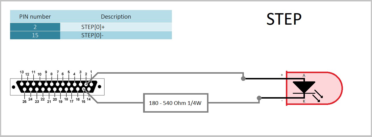
Then move the axis very slowly to see the LED flashing. If the LED is constantly on, reduce the number of pulses per mm, which will lower the LED flashing frequency. When you notice that the LED is flashing, go to the next step, if not the “step” output is damaged.
2. Change polarization and repeat step 1.
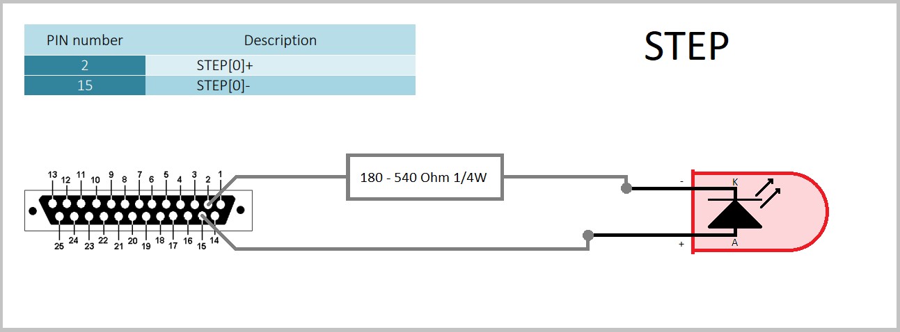
When you notice that the LED is flashing, go to the next step, if not, the “step” output is damaged.
3. Connect the LED with a 180-540 Ohm range resistor to „dir+” and „dir-” output.
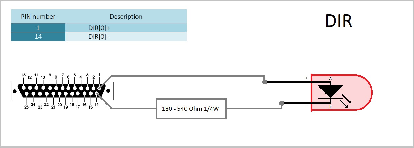
Then make a few short axis movements in the positive and negative directions. When the LED goes on and off with the change of axis movement direction, go to the next step, if not, the “dir” output is damaged.
4. Change polarization and repeat step 3.
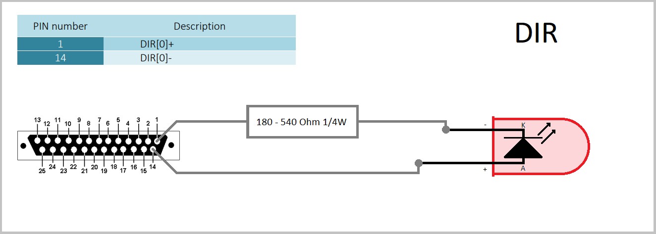
When the LED goes on and off with the change of axis direction, you have reached the end of the test, which means that the step/dir output is OK. If the LED does not go on and off at the axis direction change, the dir output is damaged. The test should be repeated in the same way with the other step/dir channels.

