


Connection drawings of the CSMIO/IP-M controller, simDrives Servo 400W, 750W (v2) and simCNC, Mach3, Mach4 software
NOTE:
Since CSMIO/IP-M has fewer 24V digital inputs, the “Servo Alarm / Servo Ready” signals between the drives were connected in series. This connection method reduces the number of required digital inputs from three to one. One consequence of this solution is that the control software will always report an error on all drives. This is not a problem because the driver signals the error with its own LED diode located on a housing.
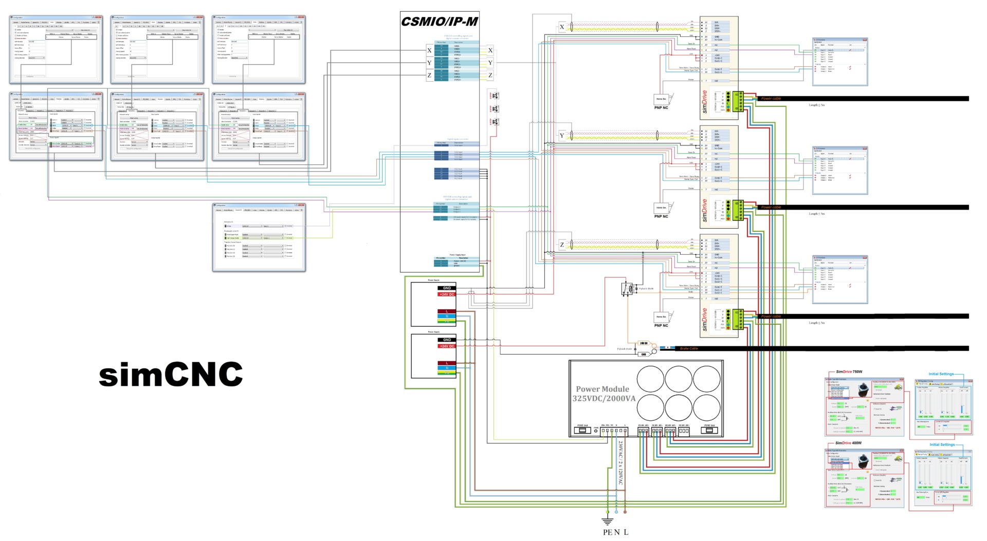
1. CSMIO/IP-M controller, simDrives Servo, and simCNC software – connection and settings (with brake)
![]() Open the PDF file for larger drawing details
Open the PDF file for larger drawing details
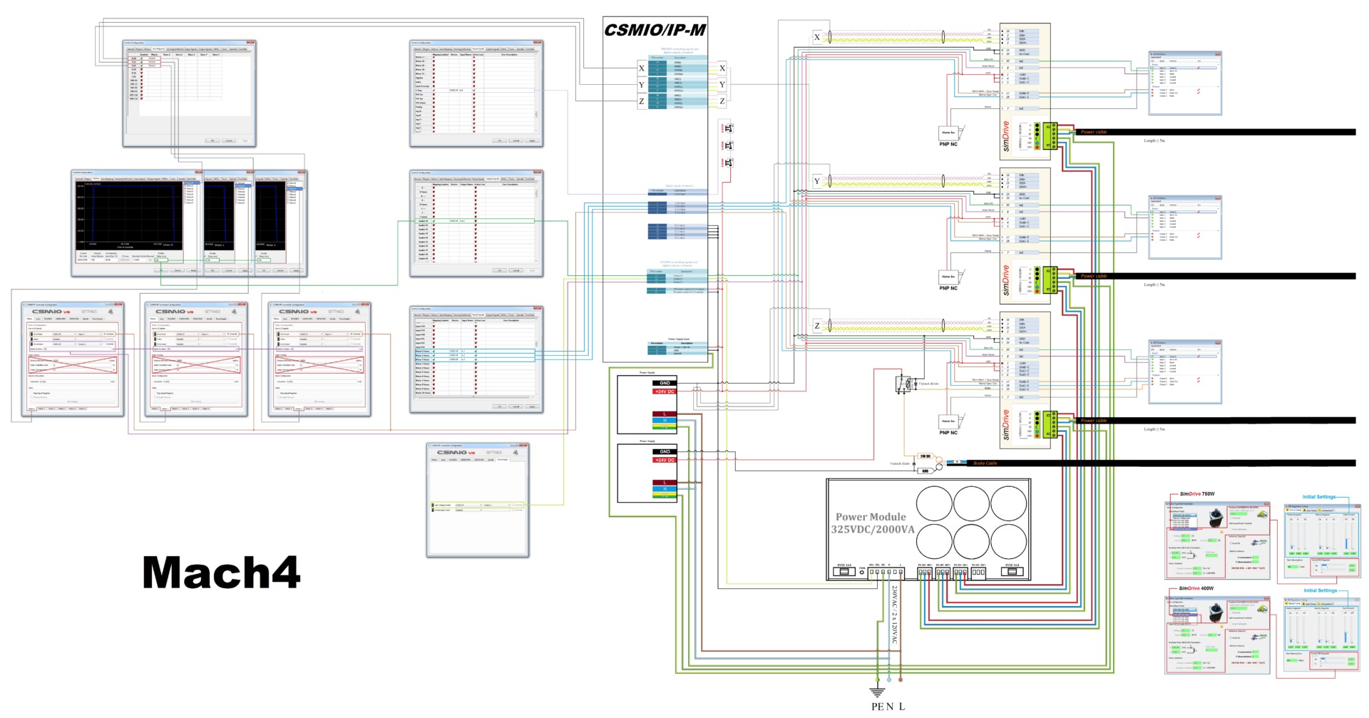
2. CSMIO/IP-M controller, simDrives Servo and Mach4 software – connection and settings (with brake)
![]() Open the PDF file for larger drawing details
Open the PDF file for larger drawing details
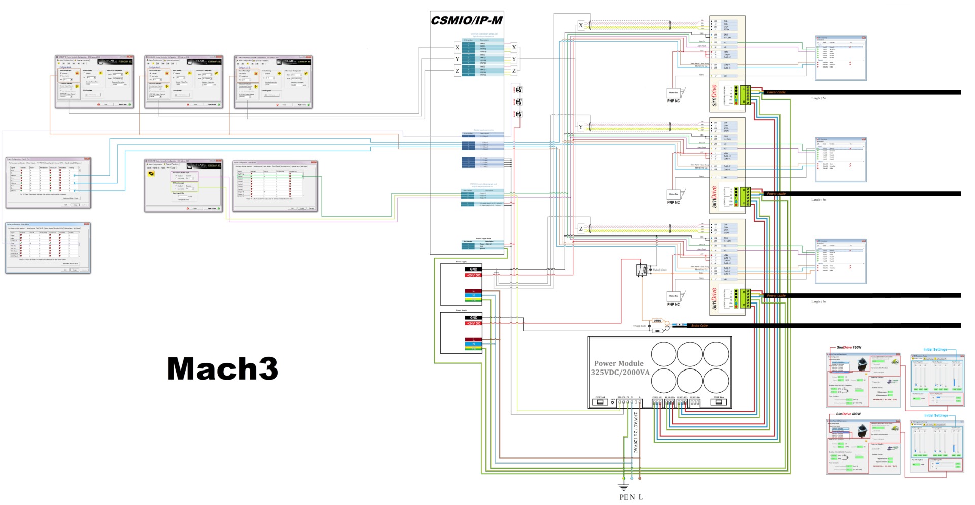
3. CSMIO/IP-M controller, simDrives Servo and Mach3 software – connection and settings (with brake)
![]() Open the PDF file for larger drawing details
Open the PDF file for larger drawing details
[Source:] The diagram was created by CS-Lab’s Technical Support section for CSMIO/IP users.
