
CS-Lab Support Forum for CNC Community
Help to run this brand-new forum and stay with us.
Ask your questions, we are here to help!
Does anyone know how to setup SimCNC to use multiple spindles?
Quote from Ozemale6t9 on 7 May 2023, 12:21Hello All,
I have a machine running SimCNC via a CSMIO/IP-A which has 2 spindles.
I can control either spindle by changing the relevant outputs in the settings screen, but I'd like to be able to run M3/M4/M5 for spindle 1 and M13/M14/M15 for spindle 2.
My setup requires DO4 or DO5 to enable the relevant spindle, then DO6/DO7 & AO0 or DO8/DO9 & AO1 to control them. The 2 spindles also have different maximum speeds, which requires that value to be changed as well.
Is there a way to change the settings values "on the fly", via Python script (without disable/re-enable)?
regards, Oz
Hello All,
I have a machine running SimCNC via a CSMIO/IP-A which has 2 spindles.
I can control either spindle by changing the relevant outputs in the settings screen, but I'd like to be able to run M3/M4/M5 for spindle 1 and M13/M14/M15 for spindle 2.
My setup requires DO4 or DO5 to enable the relevant spindle, then DO6/DO7 & AO0 or DO8/DO9 & AO1 to control them. The 2 spindles also have different maximum speeds, which requires that value to be changed as well.
Is there a way to change the settings values "on the fly", via Python script (without disable/re-enable)?
regards, Oz
Quote from CS-Lab Support on 8 May 2023, 14:08Currently, simCNC does not support two spindles (maybe in the future), and therefore, you need to change your concept.
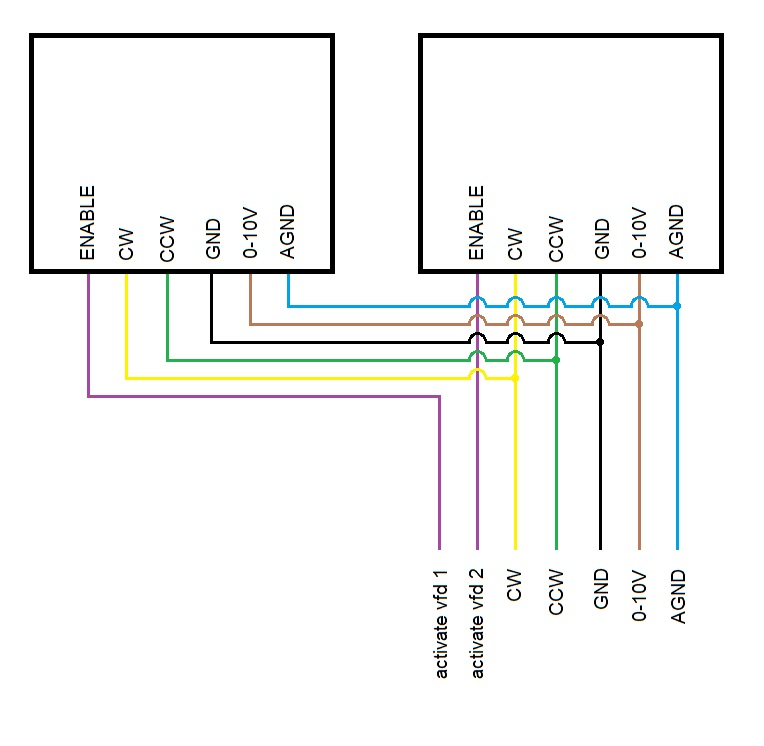
I think about using the same signals for both spindles (CW, CCW, 0-10V) and switching between VFDs with the ENABLE signal.
This will limit the number of outputs used and simplify it for simCNC.
For this to work, you need to find the enable signal in the VFD (this signal will activate the choiced VFD).
See the diagram below:
Check if it's possible and let me know, then I'll write a macro for you.
Currently, simCNC does not support two spindles (maybe in the future), and therefore, you need to change your concept.
I think about using the same signals for both spindles (CW, CCW, 0-10V) and switching between VFDs with the ENABLE signal.
This will limit the number of outputs used and simplify it for simCNC.
For this to work, you need to find the enable signal in the VFD (this signal will activate the choiced VFD).
See the diagram below:
Check if it's possible and let me know, then I'll write a macro for you.
Quote from Ozemale6t9 on 13 May 2023, 14:10Hi, and thanks for your answer.
Sure, the machine can be electrically configured as per your diagram, but this does not change the settings values which are ultimately where the problem lies.
One spindle is used for roughing and has maximum 10000 rpm, and the other is a finishing spindle with 20000 rpm maximum.
Hi, and thanks for your answer.
Sure, the machine can be electrically configured as per your diagram, but this does not change the settings values which are ultimately where the problem lies.
One spindle is used for roughing and has maximum 10000 rpm, and the other is a finishing spindle with 20000 rpm maximum.
Quote from Michael Moe on 21 September 2023, 23:39This may be a late response, but maybe it will help someone. Having set up a similar machine, the best way to do this is to use relays to forward the M3 signal to either or all heads. To do this, I use M31, M32, M33, and M34 for heads 1, 2, 3 and 4 respectively. The code to turn on a spindle is M3 M31 S***** for head one, M3 M32 S***** for head 2 and so on. Obviously, reverse would just be M4 instead of M3 and you need another set of relays specifically for that feature if you want it, but the M code for the head remains the same for post processor purposes. The speed signal is sent to all VFDs, but since the M31 (etc) relay controls whether the run signal is sent to the VFD, the speed signal is only utilized by the VFDs that receive the run signal.
In this way, you can run any individual spindle or multiple spindles simultaneously, but they will all run at the same speed if run at the same time. When you perform a tool change from one head to another, the S value should be updated through your program post processor, so you will get speed changes from head to head when used that way.
The main advantage of this system over what you initially proposed is that getting the controller to perform the task is only half of the equation. The other half is getting the output from a CAM post processor to automate the change between heads. Part of the problem there is that each head needs to be tied to a different work coordinate system to be used as a tool changer. By using M3 for all heads, then using M31, M32, etc., (or make up your own head M values), you can then output G54 for M31, G55 for M32, G56 for M33, etc. by running scripts that use math to add letters/number to the tool number. So tool 1 is "M3(tool number)" and the coordinate value is G53+(tool number). Your code for tool changes can then be output automatically to be something like this:
M3 M31 S10000 (tool 1 - roughing tool)
G54
c0de.................
M5
M3 M32 S20000 (tool 2 - finishing tool)
G55
code...........
M5
You can then calibrate the head/tool offsets so that they align perfectly with each other using the work coordinates. The organization of the machine as I've described makes the G code output much easier to get from every software package I've tried to use. In some cases, it takes a lot of tricks to find a way to tie the M code and work coordinate system to the correct head, but I have yet to encounter a software package that can't be tricked into doing it somehow. You just have to get creative there sometimes and other times it's easy.
This may be a late response, but maybe it will help someone. Having set up a similar machine, the best way to do this is to use relays to forward the M3 signal to either or all heads. To do this, I use M31, M32, M33, and M34 for heads 1, 2, 3 and 4 respectively. The code to turn on a spindle is M3 M31 S***** for head one, M3 M32 S***** for head 2 and so on. Obviously, reverse would just be M4 instead of M3 and you need another set of relays specifically for that feature if you want it, but the M code for the head remains the same for post processor purposes. The speed signal is sent to all VFDs, but since the M31 (etc) relay controls whether the run signal is sent to the VFD, the speed signal is only utilized by the VFDs that receive the run signal.
In this way, you can run any individual spindle or multiple spindles simultaneously, but they will all run at the same speed if run at the same time. When you perform a tool change from one head to another, the S value should be updated through your program post processor, so you will get speed changes from head to head when used that way.
The main advantage of this system over what you initially proposed is that getting the controller to perform the task is only half of the equation. The other half is getting the output from a CAM post processor to automate the change between heads. Part of the problem there is that each head needs to be tied to a different work coordinate system to be used as a tool changer. By using M3 for all heads, then using M31, M32, etc., (or make up your own head M values), you can then output G54 for M31, G55 for M32, G56 for M33, etc. by running scripts that use math to add letters/number to the tool number. So tool 1 is "M3(tool number)" and the coordinate value is G53+(tool number). Your code for tool changes can then be output automatically to be something like this:
M3 M31 S10000 (tool 1 - roughing tool)
G54
c0de.................
M5
M3 M32 S20000 (tool 2 - finishing tool)
G55
code...........
M5
You can then calibrate the head/tool offsets so that they align perfectly with each other using the work coordinates. The organization of the machine as I've described makes the G code output much easier to get from every software package I've tried to use. In some cases, it takes a lot of tricks to find a way to tie the M code and work coordinate system to the correct head, but I have yet to encounter a software package that can't be tricked into doing it somehow. You just have to get creative there sometimes and other times it's easy.
Quote from Ozemale6t9 on 23 September 2023, 01:48Perhaps I am not being clear enough...my problem is more related to parameter settings, not the electrical connections to make it work. I already have it working electrically, but have to change the MaxRPM parameter each time I swap spindles.
If I set a maximum rpm of 10000 for spindle 1, running spindle 2 will also only do a maximum of 10000 rpm (not 20000).
If I set a maximum rpm of 20000 to suit spindle 2, commanding spindle 1 to run at 10000 will have it run at 5000 rpm since the analogue output is 5V (10000/20000*10).
I really need to be able to write a new MaxRPM parameter "on the fly" via a macro.
Perhaps I am not being clear enough...my problem is more related to parameter settings, not the electrical connections to make it work. I already have it working electrically, but have to change the MaxRPM parameter each time I swap spindles.
If I set a maximum rpm of 10000 for spindle 1, running spindle 2 will also only do a maximum of 10000 rpm (not 20000).
If I set a maximum rpm of 20000 to suit spindle 2, commanding spindle 1 to run at 10000 will have it run at 5000 rpm since the analogue output is 5V (10000/20000*10).
I really need to be able to write a new MaxRPM parameter "on the fly" via a macro.
Quote from Michael Moe on 25 September 2023, 01:26Are you using two identical VFDs and two identical spindles or are they sharing a VFD or different spindles?
Are you using two identical VFDs and two identical spindles or are they sharing a VFD or different spindles?
Quote from Dobbelju on 27 September 2023, 09:34
Hello,
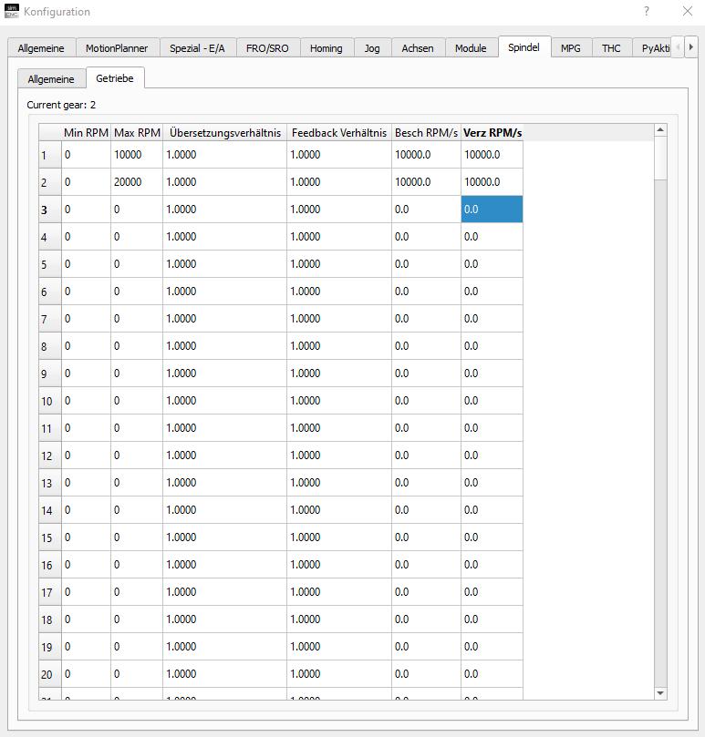
did you try to use the spindle gears?
And change them with the macro command "d.setSpindleGear( GearNumber )"?
There you can define different max / min speeds for each gear, so when you control 2 spindles with one controller it should be possible with this.
Hello,
did you try to use the spindle gears?
And change them with the macro command "d.setSpindleGear( GearNumber )"?
There you can define different max / min speeds for each gear, so when you control 2 spindles with one controller it should be possible with this.
Uploaded files:
Quote from Ozemale6t9 on 27 September 2023, 12:56Quote from Michael Moe on 25 September 2023, 01:26Are you using two identical VFDs and two identical spindles or are they sharing a VFD or different spindles?
I have 2 identical VFDs, and the servos and spindles are identical, but the pulley/belt configuration is different.
The internal parameters in the drives are different to accommodate the different maximum spindle rpm, and the drives provide analogue output of rpm back to the motion controller.
Quote from Michael Moe on 25 September 2023, 01:26Are you using two identical VFDs and two identical spindles or are they sharing a VFD or different spindles?
I have 2 identical VFDs, and the servos and spindles are identical, but the pulley/belt configuration is different.
The internal parameters in the drives are different to accommodate the different maximum spindle rpm, and the drives provide analogue output of rpm back to the motion controller.
Quote from Ozemale6t9 on 27 September 2023, 13:02Quote from Dobbelju on 27 September 2023, 09:34
Hello,
did you try to use the spindle gears?
And change them with the macro command "d.setSpindleGear( GearNumber )"?
There you can define different max / min speeds for each gear, so when you control 2 spindles with one controller it should be possible with this.
I had thought of using gears, but wasn't sure how to call it.
This may solve the problem, if I can set overlapping speed ranges.
I'll give this a try on the weekend if I get time.
Quote from Dobbelju on 27 September 2023, 09:34
Hello,
did you try to use the spindle gears?
And change them with the macro command "d.setSpindleGear( GearNumber )"?
There you can define different max / min speeds for each gear, so when you control 2 spindles with one controller it should be possible with this.
I had thought of using gears, but wasn't sure how to call it.
This may solve the problem, if I can set overlapping speed ranges.
I'll give this a try on the weekend if I get time.
PARTNERS:

USA

Germany
![]()
Slovenia / Bosnia

Spain

South Africa
The Netherlands
![]()
Portugal

Greece
![]()
Hungary

Bulgaria
![]()
Kenya

Egypt

China

Serbia

Italy

Denmark

Finland