
CS-Lab Support Forum for CNC Community
Help to run this brand-new forum and stay with us.
Ask your questions, we are here to help!
simCNC change image via Py
Quote from andre on 11 May 2023, 12:58Good afternoon!
I am currently migrating to simCNC and need a hint on a few points for my tool magazine screen.
- I have about 70 tools but the magazine I am building will hold only 30 at a time. Therefore I am decoupling tool ID and tool position in magazine. In Mach3 I used a custom-DRO as input, which would stay persistent even when restarting the software. Are there any custom fields (planned) for the tool table or any other way to effectively store inputs in simCNC?
- When a tool is assigned to a magazine position, depending on its type (extracted from tool name, i.e. FEM_ for Flat Endmill) a different image is selected. My first idea was to use CSS and set an background-image via setAttribute() from Python... is this CSS element supported or is there a better way to achieve my idea?
- I am having trouble finding the screen.css on MacOS (and actually the whole screen folder). Can somebody enlighten me, please?
Thanks!
André, happy CSMIO user since 2015
Good afternoon!
I am currently migrating to simCNC and need a hint on a few points for my tool magazine screen.
- I have about 70 tools but the magazine I am building will hold only 30 at a time. Therefore I am decoupling tool ID and tool position in magazine. In Mach3 I used a custom-DRO as input, which would stay persistent even when restarting the software. Are there any custom fields (planned) for the tool table or any other way to effectively store inputs in simCNC?
- When a tool is assigned to a magazine position, depending on its type (extracted from tool name, i.e. FEM_ for Flat Endmill) a different image is selected. My first idea was to use CSS and set an background-image via setAttribute() from Python... is this CSS element supported or is there a better way to achieve my idea?
- I am having trouble finding the screen.css on MacOS (and actually the whole screen folder). Can somebody enlighten me, please?
Thanks!
André, happy CSMIO user since 2015
Quote from CS-Lab Support on 12 May 2023, 08:321) You can use a machine parameter (1 to 4000).
The first thousand parameters are permanently stored, the second, third, and fourth are volatile.To save/read a machine parameter from the macro level, use the following commands:
d.setMachineParam( int paramNumber, float value )
d.getMachineParam( int paramNumber )You can also display and overwrite the parameter from the screen.
To do this, in the screen editor for LineEdit, set, for example, parameter number 20:
To write and read parameters from Gcode
Read : G43H(#20)
Record : #20 = 5
Arithmetic operations are also possible: #100 = #101 - #102The last option is to view and edit parameters from the parameter table:
2) It's possible, but I've never tested it with a transparent image background.
Example: gui.edJogStep.setAttribute("styleSheet", "background-color: red;")
"edJogStep" is the Id of the screen object.
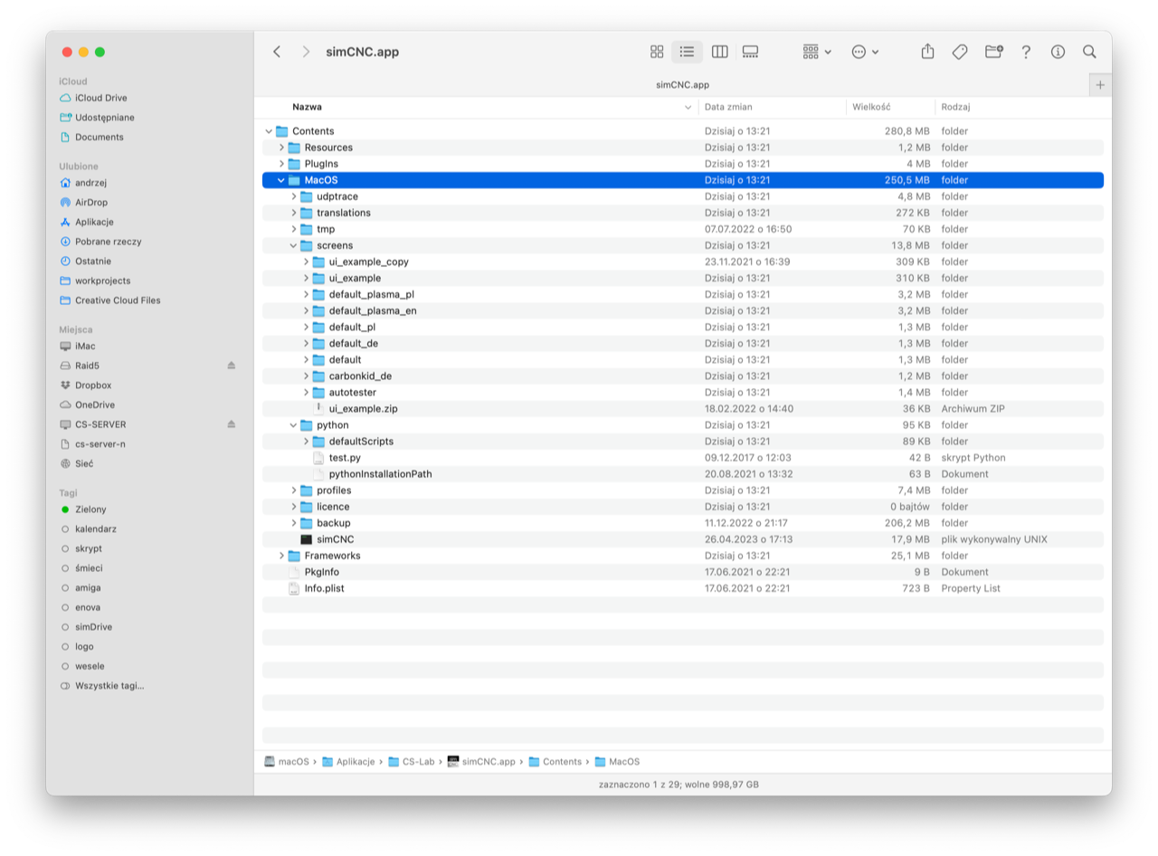
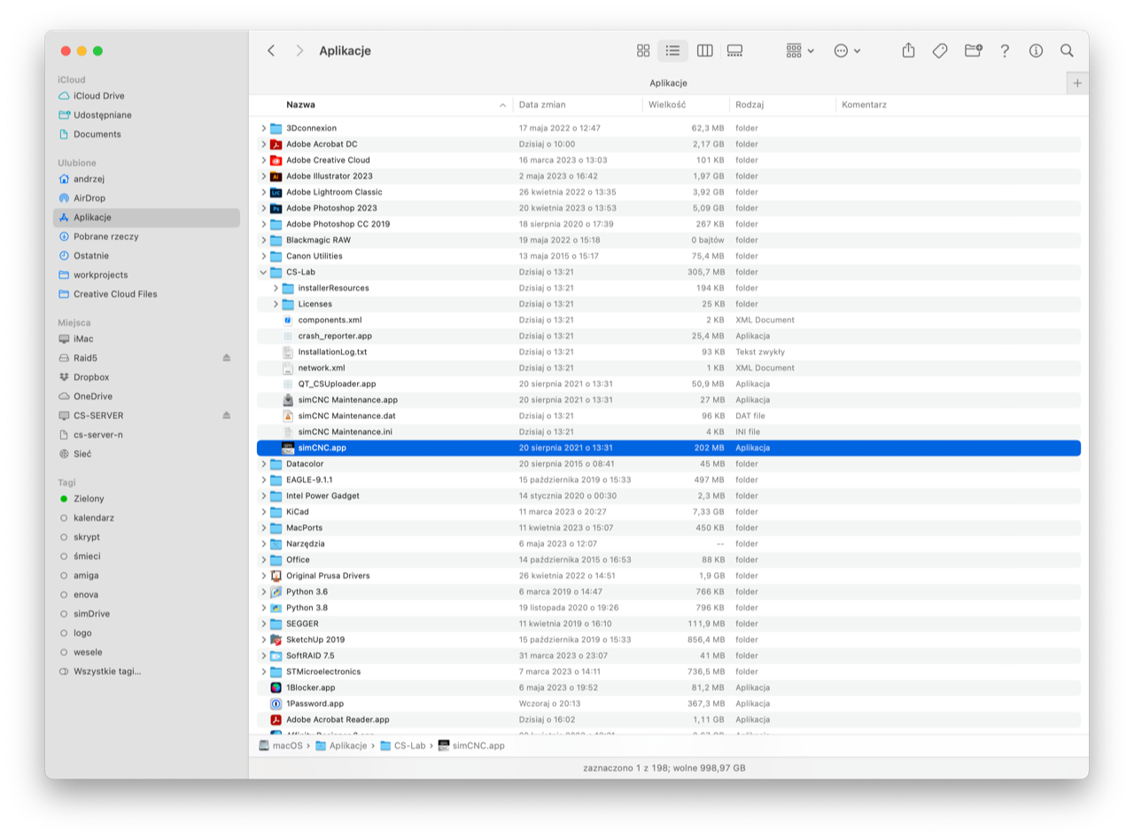
3) You must select the "Show Package Contents" option of the application (photos attached).
1) You can use a machine parameter (1 to 4000).
The first thousand parameters are permanently stored, the second, third, and fourth are volatile.
To save/read a machine parameter from the macro level, use the following commands:
d.setMachineParam( int paramNumber, float value )
d.getMachineParam( int paramNumber )
You can also display and overwrite the parameter from the screen.
To do this, in the screen editor for LineEdit, set, for example, parameter number 20:

To write and read parameters from Gcode
Read : G43H(#20)
Record : #20 = 5
Arithmetic operations are also possible: #100 = #101 - #102
The last option is to view and edit parameters from the parameter table:

2) It's possible, but I've never tested it with a transparent image background.
Example: gui.edJogStep.setAttribute("styleSheet", "background-color: red;")
"edJogStep" is the Id of the screen object.
3) You must select the "Show Package Contents" option of the application (photos attached).
Uploaded files:
Quote from andre on 12 May 2023, 11:35Thank you very much for the quick and very comprehensive support!
Love the modern approach on the GUI using CSS... very helpful.
Thank you very much for the quick and very comprehensive support!
Love the modern approach on the GUI using CSS... very helpful.
Quote from CS-Lab Support on 15 May 2023, 09:41As a curiosity, I will add that in simCNC there are also possible hint clouds:
# plain text
gui.btnJogMode.setAttribute("toolTip", "Test 123")
# HTML
gui.btnJogMode.setAttribute("toolTip", "<html><head><style>.red-bold {color: red; font-weight: bold;}</style></head><body><span class=\"red-bold\">Test 123</span></body></html>”)
As a curiosity, I will add that in simCNC there are also possible hint clouds:
# plain text
gui.btnJogMode.setAttribute("toolTip", "Test 123")
# HTML
gui.btnJogMode.setAttribute("toolTip", "<html><head><style>.red-bold {color: red; font-weight: bold;}</style></head><body><span class=\"red-bold\">Test 123</span></body></html>”)
Quote from andre on 15 May 2023, 13:01Thanks! Good to know, the tooltips could become handy.
During the weekend I started working on my screen and there are a few things I need some help with...
- Background-color and attribute works for frame but not group box or the tab box (In your ui_examle screen I can see that its possible, but could not find any hint in the screen.css), is there any trick I am missing?
- Tab box: Can the tab labels be formatted via CSS. I need to enlarge them for touchscreen use.
- GUI editor CSS does not work for me (macOS, simCNC 3.423), neither with #id nor full reference. Same style works in style.css
- Is CSS for GCode List cotent possible? (i.e. change axis colors or colors of keywords?)
- Is it possible to calculate the min/max position per Axis when a GCode was loaded? i.e. to calculate the "distance to go" per axis
- Have you thought of an On Screen Keyboard to enter numbers into a line edit (touchscreen users)? Alternatively I could try something on OS level, but they are usually a bit bulky and do not integrate nicely
- Tool magazine position: The proposed solutions with machine parameters worked fine, thank you again! Is there any plan to include "pocket number" for the tool table as a standard?
Thanks you a ton!
André
Thanks! Good to know, the tooltips could become handy.
During the weekend I started working on my screen and there are a few things I need some help with...
- Background-color and attribute works for frame but not group box or the tab box (In your ui_examle screen I can see that its possible, but could not find any hint in the screen.css), is there any trick I am missing?
- Tab box: Can the tab labels be formatted via CSS. I need to enlarge them for touchscreen use.
- GUI editor CSS does not work for me (macOS, simCNC 3.423), neither with #id nor full reference. Same style works in style.css
- Is CSS for GCode List cotent possible? (i.e. change axis colors or colors of keywords?)
- Is it possible to calculate the min/max position per Axis when a GCode was loaded? i.e. to calculate the "distance to go" per axis
- Have you thought of an On Screen Keyboard to enter numbers into a line edit (touchscreen users)? Alternatively I could try something on OS level, but they are usually a bit bulky and do not integrate nicely
- Tool magazine position: The proposed solutions with machine parameters worked fine, thank you again! Is there any plan to include "pocket number" for the tool table as a standard?
Thanks you a ton!
André
Quote from CS-Lab Support on 16 May 2023, 08:281) Of course, it's possible.
a) From CSS file:
[id="grFro"] {
background-color: red;
}
b) From the screen editor (“CSS” field):
#id {
background-color: red;
}
2. Objects should not be resized with a CSS file. CSS files are mainly used to adjust the appearance. I mean:
- change of colors
- shading
- font size and type
The size of the objects is set in the GUI editor by specifying the aspect ratio of an object size and the minimum width and height. This causes the screen to be dynamically scaled to the size of a monitor. To manage the proportion of the size of objects, they must be in "Layout," so you can use the "stretch" option.
A great example is the top row of buttons in simCNC:
All values 1 are for buttons, value 10 is for MDI lines. There may be an option to resize an object via a CSS file, but we've never used it. That's why we used a ready-made CSS solution, because it gives great possibilities.
3) Check if you accidentally refer to one object from two different places. If you change the object properties from the CSS file and from the GUI editor (CSS field) at the same time, one overwrites the other. All the CSS files and CSS fields from the GUI editor are glued together into one huge CSS file. If you change the object's properties twice in this huge file, the last one will work.
4) Yes.
Changing color of an axis and keywords is done in the "colors.css" file
5) Some time ago, I asked developers to add it.
6) This is what we thought; it will be our own keyboard (not a system one). We will do it when we have some time, currently, we are launching a new CSMIO/IP-S H7 controller with 32MB RAM.
7) It's already here. The pocket number is T, and the offset number is H.
The tool table will undergo changes soon, I mean its expansion for the needs of lathe support.
1) Of course, it's possible.

a) From CSS file:
[id="grFro"] {
background-color: red;
}
b) From the screen editor (“CSS” field):
#id {
background-color: red;
}
2. Objects should not be resized with a CSS file. CSS files are mainly used to adjust the appearance. I mean:
- change of colors
- shading
- font size and type
The size of the objects is set in the GUI editor by specifying the aspect ratio of an object size and the minimum width and height. This causes the screen to be dynamically scaled to the size of a monitor. To manage the proportion of the size of objects, they must be in "Layout," so you can use the "stretch" option.
A great example is the top row of buttons in simCNC:

All values 1 are for buttons, value 10 is for MDI lines. There may be an option to resize an object via a CSS file, but we've never used it. That's why we used a ready-made CSS solution, because it gives great possibilities.
3) Check if you accidentally refer to one object from two different places. If you change the object properties from the CSS file and from the GUI editor (CSS field) at the same time, one overwrites the other. All the CSS files and CSS fields from the GUI editor are glued together into one huge CSS file. If you change the object's properties twice in this huge file, the last one will work.
4) Yes.
Changing color of an axis and keywords is done in the "colors.css" file
5) Some time ago, I asked developers to add it.
6) This is what we thought; it will be our own keyboard (not a system one). We will do it when we have some time, currently, we are launching a new CSMIO/IP-S H7 controller with 32MB RAM.
7) It's already here. The pocket number is T, and the offset number is H.

The tool table will undergo changes soon, I mean its expansion for the needs of lathe support.
Quote from andre on 20 May 2023, 16:24Thank you very much again for taking the time to share all the details with me!
1. and 3. looked like an issue with my OS or installation... I reinstalled simCNC and now its working.
2. Generally clear on the layout vs. design choices for CSS, but I was looking for a way to adjust the tabwidget tab handle heigth and text format to make it more accessible for touchscreen use.
7. Sort of what I was looking for...My starting point: I have 20 pockets in the tool magazine but use about 50 different tools in my CAM. To keep tool numbers stay the same in CAM, I need to be able to assign any tool number to one of the 20 pockets, depending on the project I am milling. Before running the project I would re-stock the magazine accordingly. i.e. pocket 1 = tool 50, pocket 2 = tool 23.
The current tool table - to my understanding - has a fixed relation between column H and T (at least read only from GUI).Some additional things I came across, sorry for the ton of questions!
8. Will the future tool table update have a text field for adding a name to the tool? I cannot edit column "Tool", so I would need to store this manually as machine parameter at the moment.
9. Is there a getToolInfo(toolNumber) function planned or is the only way to pick all tool relevant information from the machineParameters 6018-8049 / 11000 following?
10. I would like to use border attribute for objects, at least for frames. I cannot get it to work (see 2nd blue block). Any tricks here?
In general it would be great to have an overview which widgets support which HTML parameters. i.e. I was trying to set visibility / opacity for buttons, but it did not work.
11. I was trying to create a progress bar which goes bottom to top (vertical), but the setting does not change the behavior. Both orientation setting result in the same behavior.
Thank you very much again for taking the time to share all the details with me!
1. and 3. looked like an issue with my OS or installation... I reinstalled simCNC and now its working.
2. Generally clear on the layout vs. design choices for CSS, but I was looking for a way to adjust the tabwidget tab handle heigth and text format to make it more accessible for touchscreen use.

7. Sort of what I was looking for...My starting point: I have 20 pockets in the tool magazine but use about 50 different tools in my CAM. To keep tool numbers stay the same in CAM, I need to be able to assign any tool number to one of the 20 pockets, depending on the project I am milling. Before running the project I would re-stock the magazine accordingly. i.e. pocket 1 = tool 50, pocket 2 = tool 23.
The current tool table - to my understanding - has a fixed relation between column H and T (at least read only from GUI).
Some additional things I came across, sorry for the ton of questions!
8. Will the future tool table update have a text field for adding a name to the tool? I cannot edit column "Tool", so I would need to store this manually as machine parameter at the moment.
9. Is there a getToolInfo(toolNumber) function planned or is the only way to pick all tool relevant information from the machineParameters 6018-8049 / 11000 following?
10. I would like to use border attribute for objects, at least for frames. I cannot get it to work (see 2nd blue block). Any tricks here?
In general it would be great to have an overview which widgets support which HTML parameters. i.e. I was trying to set visibility / opacity for buttons, but it did not work.

11. I was trying to create a progress bar which goes bottom to top (vertical), but the setting does not change the behavior. Both orientation setting result in the same behavior.

Quote from CS-Lab Support on 25 May 2023, 08:212) Now I understand what you meant ( thanks to the picture).
There are several ways to resize "tab":
a) From macro.
gui.tabCentral.setAttribute("styleSheet", ":tab {height: 50px; width: 160px; font-size:16pt;}")
b) From the gui editor for one QTabBar object (in the CSS window of the "tabCentral" object)
#id :tab {height: 50px; width: 160px; font-size:16pt;}")
c) From the gui editor for all QTabBar objects (in the CSS window of the "MainLayout" object)
#id :tab {height: 50px; width: 160px; font-size:16pt;}")
d) From a CSS file
[id="tabCentral"] :tab {height: 50px; width: 160px; font-size:16pt;}
e) From the CSS file for all QTabBar objects on the screen.
QTabBar::tab {height: 50px; width: 160px; font-size:16pt;}
7) T and H in the table are not connected.
T is just the pocket number in your magazine and H is its length. How you want to use your machine fits perfectly with what I wrote above (i.e. the current state of simCNC). In the future, we will expand the table, but we will not expand it in such a way that we change the relation between T and H.
I have a feeling that what's confusing you is your CAM program. I used to use MasteCam very long and intensively. In his case, T meant only pocket, H meant:
- type of tool
- F and S parameters
- tool length.
When I selected a previously defined tool from the CAM program library with the number e.g. 3, it resulted in placing the G43 H3 command in the code. All I had to do was set the pocket number in the CAM program, i.e. T. Check if your CAM program doesn't break this logic.
8) Yes.
9) There will be no such function because there are already functions that return all the information:
H = 2
print(d.getToolLength(H))
print(d.getToolDiameter( H ))
print(d.getToolOffset(2))
print(d.getToolWearOffset( H ))
print(d.getToolDiameterWear( H ))
See how it works:
10) I just tested and the border works:
#id {background-color: green; border-radius: 20px;}
#id {background-color: blue; border-radius: 20px;}
#id {background-color: red; border-radius: 20px;}
Remember that we are not CSS creators, we only use CSS in the simCNC screen.
This means that you can find plenty of examples online.
To answer your questions about CSS, I had to use examples from the web myself.
That's why I encourage you to experiment with CSS yourself.
2) Now I understand what you meant ( thanks to the picture).
There are several ways to resize "tab":
a) From macro.
gui.tabCentral.setAttribute("styleSheet", ":tab {height: 50px; width: 160px; font-size:16pt;}")
b) From the gui editor for one QTabBar object (in the CSS window of the "tabCentral" object)
#id :tab {height: 50px; width: 160px; font-size:16pt;}")
c) From the gui editor for all QTabBar objects (in the CSS window of the "MainLayout" object)
#id :tab {height: 50px; width: 160px; font-size:16pt;}")
d) From a CSS file
[id="tabCentral"] :tab {height: 50px; width: 160px; font-size:16pt;}
e) From the CSS file for all QTabBar objects on the screen.
QTabBar::tab {height: 50px; width: 160px; font-size:16pt;}
7) T and H in the table are not connected.
T is just the pocket number in your magazine and H is its length. How you want to use your machine fits perfectly with what I wrote above (i.e. the current state of simCNC). In the future, we will expand the table, but we will not expand it in such a way that we change the relation between T and H.
I have a feeling that what's confusing you is your CAM program. I used to use MasteCam very long and intensively. In his case, T meant only pocket, H meant:
- type of tool
- F and S parameters
- tool length.
When I selected a previously defined tool from the CAM program library with the number e.g. 3, it resulted in placing the G43 H3 command in the code. All I had to do was set the pocket number in the CAM program, i.e. T. Check if your CAM program doesn't break this logic.
8) Yes.
9) There will be no such function because there are already functions that return all the information:
H = 2
print(d.getToolLength(H))
print(d.getToolDiameter( H ))
print(d.getToolOffset(2))
print(d.getToolWearOffset( H ))
print(d.getToolDiameterWear( H ))
See how it works:

10) I just tested and the border works:
#id {background-color: green; border-radius: 20px;}
#id {background-color: blue; border-radius: 20px;}
#id {background-color: red; border-radius: 20px;}

Remember that we are not CSS creators, we only use CSS in the simCNC screen.
This means that you can find plenty of examples online.
To answer your questions about CSS, I had to use examples from the web myself.
That's why I encourage you to experiment with CSS yourself.
Quote from andre on 25 May 2023, 10:55Thanks once more for the details and the fast support on my customizing questions. Really appreciate it!
2. Formatting tab handles
I was exactly looking for the pseudo-class "tab".
From your example I realized that the user interface is based on QT, so I will be able to refer to general QT documentation going forward. Less questions here 🙂10. CSS border
Thanks for the detailed check! I used the same classes and identifiers in my test - let me try on a Windows machine, I have the feeling that there is an issue with my MacOS.CSS is not new to me, I have almost 20y of web-dev experience. But in connection with simCNC I was struggeling with unexpected behavior (the above topic) as well as finding the right classes and pseudo-classes the GUI uses (which should be solved by point 2 now).
7. Tool pocket # vs. CAM
I am using Fusion360 as CAM, but I guess MasterCam is similar.Maybe it's a mispereception/unusual (unnescessary?) concept in my head - I want to achieve fixed tool numbers in CAM but flexible pocket assignments on the machine. Otherwise I need to change tool numbers every time in CAM to match tool setup in pocket. Also, my endmill-drawer is organized by tool numbers. T10 for example is a 8mm 45° chamfer mill.
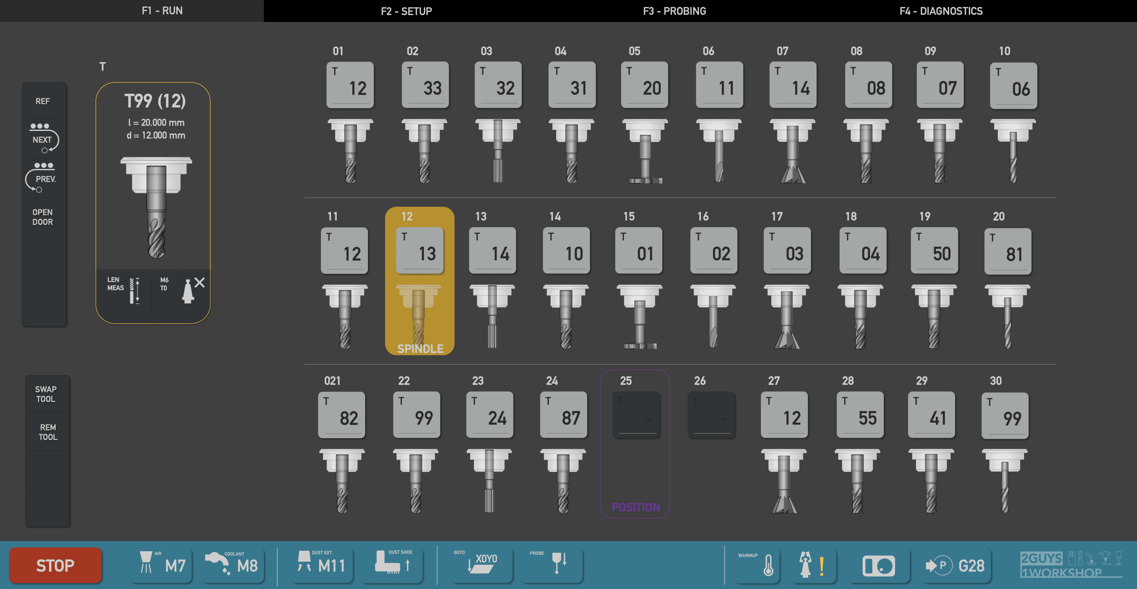
Here is what my screen in simCNC currently looks like with a 20 position magazine:
And my CAM/machine process:
- CAM: All my 50 tools are set up and numbered in ranges by material:
i.e. #10-39 is aluminum tools, #40-59 is wood tools, etc.- Machine: All my 50 tools are in the tool table with corresponding tool numbers from CAM. If a tool is not loaded into magazine, pocket is "0" (which will trigger manual tool change when M6 is called).
Of course there can also be gaps, in case for example I have no wood-tool 50-59 but a tool 60 for acrylics.- When I output GCode for a wood project, I use the CAM setup sheet to place the corresponding tools into the magazine.
- i.e. Pocket 1 -> T42, Pocket 2 -> T45, Pocket 3 -> T49
- Gcode for example calls M6 T42 in first op, which according to the mapping is set to pocket 1
Easiest way to achieve this would be to create custom machine parameters like you suggested initially. No problem.
And for the tool table text field from point 8 I will wait until future version, not so critical.Wielkie dzięki,
André
Thanks once more for the details and the fast support on my customizing questions. Really appreciate it!
2. Formatting tab handles
I was exactly looking for the pseudo-class "tab".
From your example I realized that the user interface is based on QT, so I will be able to refer to general QT documentation going forward. Less questions here 🙂
10. CSS border
Thanks for the detailed check! I used the same classes and identifiers in my test - let me try on a Windows machine, I have the feeling that there is an issue with my MacOS.
CSS is not new to me, I have almost 20y of web-dev experience. But in connection with simCNC I was struggeling with unexpected behavior (the above topic) as well as finding the right classes and pseudo-classes the GUI uses (which should be solved by point 2 now).
7. Tool pocket # vs. CAM
I am using Fusion360 as CAM, but I guess MasterCam is similar.
Maybe it's a mispereception/unusual (unnescessary?) concept in my head - I want to achieve fixed tool numbers in CAM but flexible pocket assignments on the machine. Otherwise I need to change tool numbers every time in CAM to match tool setup in pocket. Also, my endmill-drawer is organized by tool numbers. T10 for example is a 8mm 45° chamfer mill.
Here is what my screen in simCNC currently looks like with a 20 position magazine:

And my CAM/machine process:
- CAM: All my 50 tools are set up and numbered in ranges by material:
i.e. #10-39 is aluminum tools, #40-59 is wood tools, etc. - Machine: All my 50 tools are in the tool table with corresponding tool numbers from CAM. If a tool is not loaded into magazine, pocket is "0" (which will trigger manual tool change when M6 is called).
Of course there can also be gaps, in case for example I have no wood-tool 50-59 but a tool 60 for acrylics. - When I output GCode for a wood project, I use the CAM setup sheet to place the corresponding tools into the magazine.
- i.e. Pocket 1 -> T42, Pocket 2 -> T45, Pocket 3 -> T49
- Gcode for example calls M6 T42 in first op, which according to the mapping is set to pocket 1
Easiest way to achieve this would be to create custom machine parameters like you suggested initially. No problem.
And for the tool table text field from point 8 I will wait until future version, not so critical.
Wielkie dzięki,
André
Quote from CS-Lab Support on 25 May 2023, 13:06>> Otherwise I need to change tool numbers every time in CAM to match tool setup in pocket.
That's what it's all about. In the CAM software, you select a tool from the library (select H) and assign it a pocket number (select T). This is what operators did 30 years ago when writing gcode by hand. This allowed them to keep the tool length tables (H) constant and only manipulate the pocket number (T). It was designed so operators could:
- borrow tools
- have more tools than pockets in stock
- change the order of tools, mainly in the case of a lathe, so there is no collision with the lathe chuck.
>> Also, my endmill-drawer is organized by tool numbers. T10 for example is a 8mm 45° chamfer mill.
You're thinking about it wrong. The tool is the H parameter, and the pocket in which it is located is the T parameter. If you stick to this rule, you will only have to change the T parameter in the CAM software. You have to decide whether you want to follow the standard way (as I wrote) or four own paths (as you describe).
Both ways are acceptable as long as they work correctly.
>> Otherwise I need to change tool numbers every time in CAM to match tool setup in pocket.
That's what it's all about. In the CAM software, you select a tool from the library (select H) and assign it a pocket number (select T). This is what operators did 30 years ago when writing gcode by hand. This allowed them to keep the tool length tables (H) constant and only manipulate the pocket number (T). It was designed so operators could:
- borrow tools
- have more tools than pockets in stock
- change the order of tools, mainly in the case of a lathe, so there is no collision with the lathe chuck.
>> Also, my endmill-drawer is organized by tool numbers. T10 for example is a 8mm 45° chamfer mill.
You're thinking about it wrong. The tool is the H parameter, and the pocket in which it is located is the T parameter. If you stick to this rule, you will only have to change the T parameter in the CAM software. You have to decide whether you want to follow the standard way (as I wrote) or four own paths (as you describe).
Both ways are acceptable as long as they work correctly.
PARTNERS:

USA

Germany
![]()
Slovenia / Bosnia

Spain

South Africa
The Netherlands
![]()
Portugal

Greece
![]()
Hungary

Bulgaria
![]()
Kenya

Egypt

China

Serbia

Italy

Denmark

Finland