
CS-Lab Support Forum for CNC Community
Help to run this brand-new forum and stay with us.
Ask your questions, we are here to help!
CSMIO/IPA and Bosch TR25 (Deckel FP4NC)
Quote from Jef FP4NC on 4 July 2023, 11:13Hello,
i am rebuilding a Deckel FP4NC with a new CSMIO/IPA controller, which allows me to keep as much of the original parts as possible.
Now i am looking at the schematics of the Bosch TR25 controller
So far it looks like this:
On TR 25 CSMIO/IPA
(Xaxis)X11:1 Sw1+ Analog I/O Pin 1
X11:2 Sw1- Analog I/O Pin 14
(Yaxis)X21:1 Sw1+ Analog I/O Pin 2
X21:2 Sw1- Analog I/O Pin 15
(Zaxis) X31:1 Sw+ Analog I/O Pin 3
X31:2 Sw- Analog I/O Pin 16
Should I connect the enable (FG) command of the three axes (X11:8;X21:8;X31:8) together to a Digital output?
Or do these have to be individually connected for when the axis are clamped, FG can be disabled per axis?(Page 8 in the manual)
Best regards, and thank you in advance for any help. You will notice i have a lot to learn
Hello,
i am rebuilding a Deckel FP4NC with a new CSMIO/IPA controller, which allows me to keep as much of the original parts as possible.
Now i am looking at the schematics of the Bosch TR25 controller
So far it looks like this:
On TR 25 CSMIO/IPA
(Xaxis)X11:1 Sw1+ Analog I/O Pin 1
X11:2 Sw1- Analog I/O Pin 14
(Yaxis)X21:1 Sw1+ Analog I/O Pin 2
X21:2 Sw1- Analog I/O Pin 15
(Zaxis) X31:1 Sw+ Analog I/O Pin 3
X31:2 Sw- Analog I/O Pin 16
Should I connect the enable (FG) command of the three axes (X11:8;X21:8;X31:8) together to a Digital output?
Or do these have to be individually connected for when the axis are clamped, FG can be disabled per axis?(Page 8 in the manual)
Best regards, and thank you in advance for any help. You will notice i have a lot to learn
Uploaded files:
Quote from Jef FP4NC on 4 July 2023, 12:44I am also making a digital copy of the machine technical manual, i will include it here
I am also making a digital copy of the machine technical manual, i will include it here
Uploaded files:
Quote from CS-Lab Support on 5 July 2023, 07:27I have to start with the fact that your drivers are old and are made with outdated technology, which may cause some problems in connecting and running them.
1) Connection of +/-10V signal
It has become a standard not to connect GDN (i.e., 0V) with Earth (i.e., PE), thanks to which the influence of interference on analog signals is effectively limited.
Your drivers come from the era when it was considered that GDN (i.e., 0V) should be connected in every possible place with Earth (i.e., PE).
This solution was effective many years ago when the electronics were slow, supported the low resolution, and were insensitive.
Electronics are currently much more sophisticated, so this solution is abandoned.
Therefore, it is difficult to say how exactly your drivers should be connected to a modern CSMIO/IP-A controller.
Common sense, in the first place, tells you to connect it as you said:
On TR 25 CSMIO/IPA
(Xaxis)X11:1 Sw1+ Analog I/O Pin 1
X11:2 Sw1- Analog I/O Pin 14
(Yaxis)X21:1 Sw1+ Analog I/O Pin 2
X21:2 Sw1- Analog I/O Pin 15
(Zaxis) X31:1 Sw+ Analog I/O Pin 3
X31:2 Sw- Analog I/O Pin 16
If this solution turns out to be incorrect, you will have to follow the diagram below.
I mean the GND (0V) connection of the CSMIO/IP-A controller power socket with the "L-" pin of the driver.
2) Enable
>> Should I connect the enable (FG) command of the three axes (X11:8;X21:8;X31:8) together to a Digital output?
This is what you should do as it is general practice.
>>> Or do these have to be individually connected for when the axis are clamped, FG can be disabled per axis?(Page 8 in the manual)
Don't do that because it doesn't make sense, and you'll only lose a few digital outputs.
3) Feedback.
>>> Could i also connect the Tachos for PID loop, in combination with the Heidenhain glass scales?
Tacho generators must be connected to drivers, and the driver must use them!
(thanks to tacho generators, the driver can work in the speed mode, which the CSMIO/IP-A controller requires)Glass scales must be connected to the CSMIO/IP-A controller!
Pay attention to what signal your glass scales generate.
If it turns out that your glass scales generate a sinusoidal signal, you cannot connect them to the CSMIO/IP-A controller.
In this situation, there are two possible solutions:
- purchase of new incremental scales compatible with the RS422 standard
- purchase of a sinusoidal to incremental signal converter compatible with the RS422 standard.
This converter is called EXE and is also made by Heidenhain.4) Ready (BTB)
This signal is available in socket X10 and is probably the "Ready" signal of all axes (collective signal).
My observations show that the "Ready" or "BTB" signal is also present on the pins X11:6, X21:6, X31:6, X41:6.
If I'm not mistaken, these are the "Ready" signals of the individual axes. If so, you could use these signals and have information in the control software that MotionKit failed.
Regards,
Wojtek
I have to start with the fact that your drivers are old and are made with outdated technology, which may cause some problems in connecting and running them.
1) Connection of +/-10V signal
It has become a standard not to connect GDN (i.e., 0V) with Earth (i.e., PE), thanks to which the influence of interference on analog signals is effectively limited.
Your drivers come from the era when it was considered that GDN (i.e., 0V) should be connected in every possible place with Earth (i.e., PE).
This solution was effective many years ago when the electronics were slow, supported the low resolution, and were insensitive.
Electronics are currently much more sophisticated, so this solution is abandoned.
Therefore, it is difficult to say how exactly your drivers should be connected to a modern CSMIO/IP-A controller.
Common sense, in the first place, tells you to connect it as you said:
On TR 25 CSMIO/IPA
(Xaxis)X11:1 Sw1+ Analog I/O Pin 1
X11:2 Sw1- Analog I/O Pin 14
(Yaxis)X21:1 Sw1+ Analog I/O Pin 2
X21:2 Sw1- Analog I/O Pin 15
(Zaxis) X31:1 Sw+ Analog I/O Pin 3
X31:2 Sw- Analog I/O Pin 16
If this solution turns out to be incorrect, you will have to follow the diagram below.
I mean the GND (0V) connection of the CSMIO/IP-A controller power socket with the "L-" pin of the driver.

2) Enable
>> Should I connect the enable (FG) command of the three axes (X11:8;X21:8;X31:8) together to a Digital output?
This is what you should do as it is general practice.
>>> Or do these have to be individually connected for when the axis are clamped, FG can be disabled per axis?(Page 8 in the manual)
Don't do that because it doesn't make sense, and you'll only lose a few digital outputs.
3) Feedback.
>>> Could i also connect the Tachos for PID loop, in combination with the Heidenhain glass scales?
Tacho generators must be connected to drivers, and the driver must use them!
(thanks to tacho generators, the driver can work in the speed mode, which the CSMIO/IP-A controller requires)
Glass scales must be connected to the CSMIO/IP-A controller!
Pay attention to what signal your glass scales generate.
If it turns out that your glass scales generate a sinusoidal signal, you cannot connect them to the CSMIO/IP-A controller.
In this situation, there are two possible solutions:
- purchase of new incremental scales compatible with the RS422 standard
- purchase of a sinusoidal to incremental signal converter compatible with the RS422 standard.
This converter is called EXE and is also made by Heidenhain.
4) Ready (BTB)
This signal is available in socket X10 and is probably the "Ready" signal of all axes (collective signal).
My observations show that the "Ready" or "BTB" signal is also present on the pins X11:6, X21:6, X31:6, X41:6.
If I'm not mistaken, these are the "Ready" signals of the individual axes. If so, you could use these signals and have information in the control software that MotionKit failed.
Regards,
Wojtek
Quote from Jef FP4NC on 6 July 2023, 15:42
Thanks for the feedback Wojtek,
I hope to get the EXE's next week and then i can proceed,
best regards
jef
Thanks for the feedback Wojtek,
I hope to get the EXE's next week and then i can proceed,
best regards
jef
Quote from CS-Lab Support on 7 July 2023, 12:11One more quick note, the EXE circuit with optical scales requires about 350mA.
A single 5V output of the CSMIO/IP-A controller used to power the encoder or scale offers max 200mA.
If your machine has only 3 axes, you can use free 5V power outputs (connect them in pairs).
This way, instead of 6 x 200mA, you get 3 x 400mA.You must use an external 5V 2.5A power supply if that's still insufficient.
Then you must remember to connect the GND (0V) of the power supply with the GND (0V) of the encoder socket of the CSMIO/IP-A controller.
One more quick note, the EXE circuit with optical scales requires about 350mA.
A single 5V output of the CSMIO/IP-A controller used to power the encoder or scale offers max 200mA.
If your machine has only 3 axes, you can use free 5V power outputs (connect them in pairs).
This way, instead of 6 x 200mA, you get 3 x 400mA.
You must use an external 5V 2.5A power supply if that's still insufficient.
Then you must remember to connect the GND (0V) of the power supply with the GND (0V) of the encoder socket of the CSMIO/IP-A controller.
Quote from Jef FP4NC on 14 July 2023, 17:42If this solution turns out to be incorrect, you will have to follow the diagram below.
I mean the GND (0V) connection of the CSMIO/IP-A controller power socket with the "L-" pin of the driver.
This is the correct way to do it,
the way i originally wired it makes all axes "drift", they make a slow but steady motion.
Thanks for pointing this out Wojtek.
The EXE are connected, and give good readout,
but i will hook them up to a separate powersupply as you suggest.
If this solution turns out to be incorrect, you will have to follow the diagram below.
I mean the GND (0V) connection of the CSMIO/IP-A controller power socket with the "L-" pin of the driver.

This is the correct way to do it,
the way i originally wired it makes all axes "drift", they make a slow but steady motion.
Thanks for pointing this out Wojtek.
The EXE are connected, and give good readout,
but i will hook them up to a separate powersupply as you suggest.
Quote from CS-Lab Support on 17 July 2023, 12:41If you followed the recommendation below and everything works properly, then if I were you, I would abandon the idea of using an external power supply.
One more quick note, the EXE circuit with optical scales requires about 350mA.
A single 5V output of the CSMIO/IP-A controller used to power the encoder or scale offers max 200mA.
If your machine has only 3 axes, you can use free 5V power outputs (connect them in pairs).
This way, instead of 6 x 200mA, you get 3 x 400mA.
The CSMIO/IP-A controller has reusable polymer fuses, so if the EXE were too much loading, one would work.
Regards,
Wojtek
If you followed the recommendation below and everything works properly, then if I were you, I would abandon the idea of using an external power supply.
One more quick note, the EXE circuit with optical scales requires about 350mA.
A single 5V output of the CSMIO/IP-A controller used to power the encoder or scale offers max 200mA.
If your machine has only 3 axes, you can use free 5V power outputs (connect them in pairs).
This way, instead of 6 x 200mA, you get 3 x 400mA.
The CSMIO/IP-A controller has reusable polymer fuses, so if the EXE were too much loading, one would work.
Regards,
Wojtek
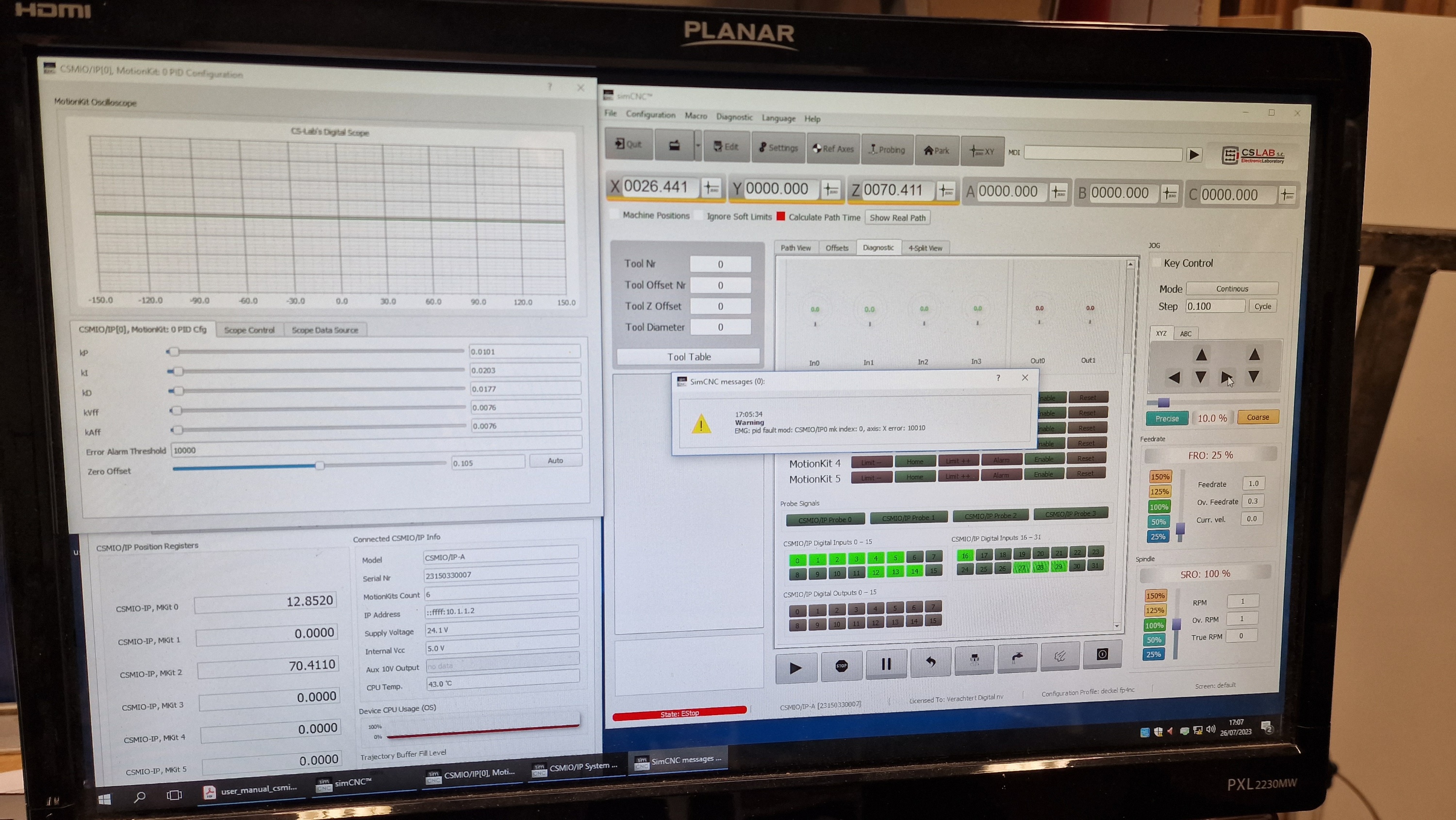
Quote from Jef FP4NC on 26 July 2023, 17:38Hi,
we can now switch on the machine, for now i disabled Y and Z axis.
At first the X-axis immediately started moving when i switched on the CSlab Console (and it then automatically shut down)
Then, with a minor adjustment of "zero offset", from 0 to 0.105 (see picture) the axis stays in place, like it should.
Additional info: when the axis moved it sounded axactly like it should, smooth.
So in this state, when i jog the x-axis left or right, it goes extremely fast, and the CSLab console gives pid error (see picture)
The PID configuration menu does look like a different version then is described in the manual(rev3).
Thanks for your guidance,
best regards, jef
Hi,
we can now switch on the machine, for now i disabled Y and Z axis.
At first the X-axis immediately started moving when i switched on the CSlab Console (and it then automatically shut down)
Then, with a minor adjustment of "zero offset", from 0 to 0.105 (see picture) the axis stays in place, like it should.
Additional info: when the axis moved it sounded axactly like it should, smooth.
So in this state, when i jog the x-axis left or right, it goes extremely fast, and the CSLab console gives pid error (see picture)
The PID configuration menu does look like a different version then is described in the manual(rev3).
Thanks for your guidance,
best regards, jef
Uploaded files:
Quote from Jef FP4NC on 27 July 2023, 13:37The solution was to reverse encoder direction, as described in the manual of CSMIO.
Now i can jog the axis nicely.
Will attempt further tuning shortly
The solution was to reverse encoder direction, as described in the manual of CSMIO.
Now i can jog the axis nicely.
Will attempt further tuning shortly
PARTNERS:

USA

Germany
![]()
Slovenia / Bosnia

Spain

South Africa
The Netherlands
![]()
Portugal

Greece
![]()
Hungary

Bulgaria
![]()
Kenya

Egypt

China

Serbia

Italy

Denmark

Finland